Some Cool Process and Parts I’ve Machined
From single point broaching a keyway to 4-axis machining a groove, I’ve make a lot of cool parts with my CNC that turned out better than I thought.
Retaining Ring
The video above shows me milling a groove in the rudders shaft for a retaining ring. I used the rudder’s servo as a 4th axis! The grove was about 1.1 mm wide.
Single point keyway broaching
I attached a piece of high speed steel ground down to the right size for my y-axis. I single point broached a keyway for my rudder. The keyway is dudes to couple th gearbox to the rudder’s shaft. Due to tool and machine deflection making the end of the keyway lower than the front I made a program the raised the z-axis while moving to compensate.
Custom Timing belts
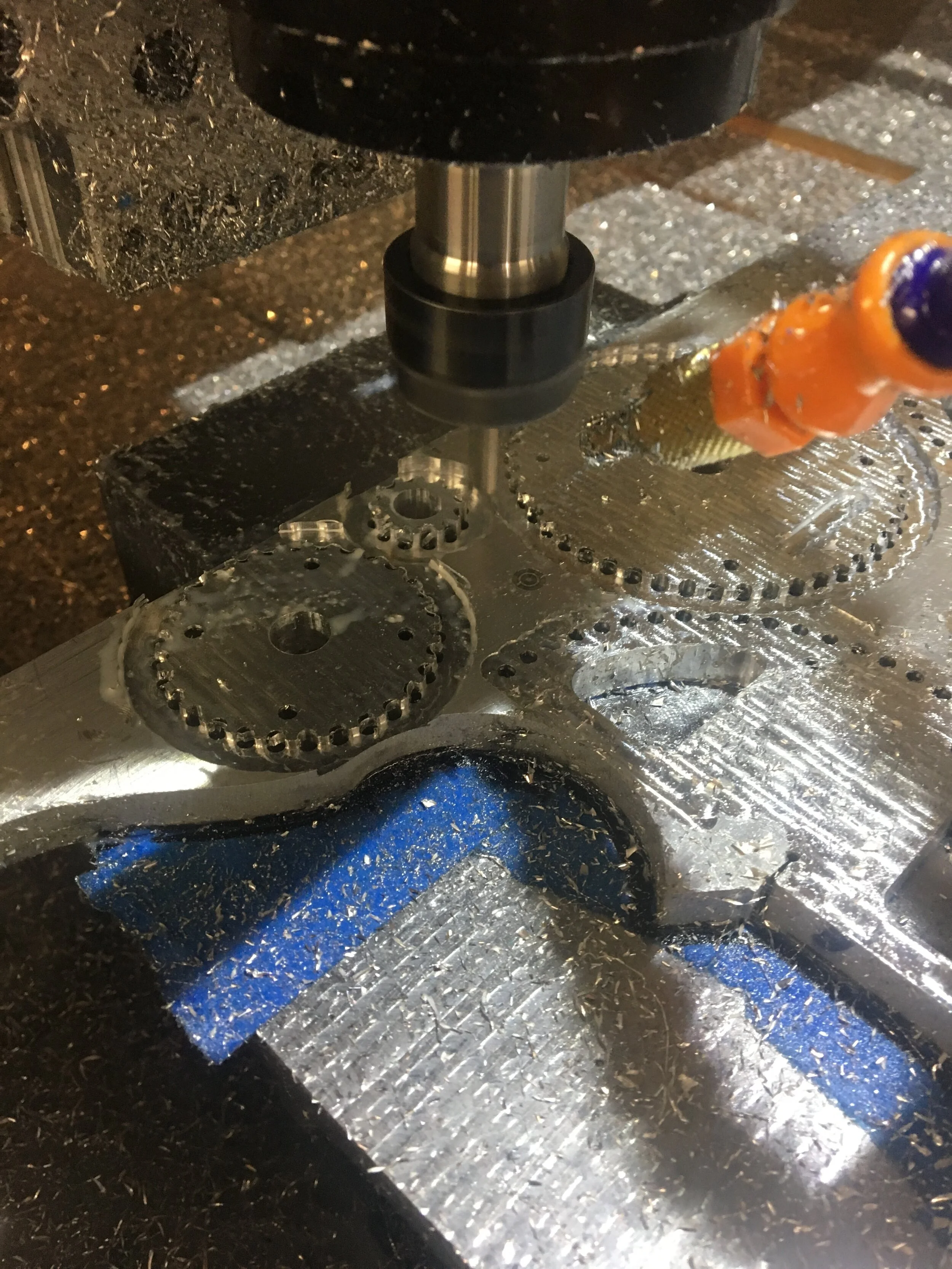
I first drilled all the “gear teeth” with a 3.05 mm. This shows part way through the drilling process which removed the bulk of the aluminum from around the timing pulley. After most of the material was removed, I used a smaller diameter endmill to finish the timing pulley’s required geometry.

This is one half of one of the gears. It was made out of two pieces so it could be bolted around the spindle’s shaft. This way it can be driven by a motor with lower RPM than my spindle motor. This allowed me to expand the capabilities of my CNC router.

The holes in the timing pulleys allowed me to be able to put a bolt to clamp the two sides together, and also they where made in a way so that the center of mass was in the center of figure so they’d be balanced. I achieved an amazing surface finish on the aluminum which you can see from the surface reflections.
Daedalus Steering Wheel Bearing

I decided to make a custom bearing with a rounded groove which I filled with 6 mm stainless ball bearings (the control panel also had rounded grooves.) An o-ring on the outside is used to keep water and dust out. I decided to make my own bearing due to not being able to find a bearing that was cheap, wouldn’t corrode when exposed to water and was the right size. My custom made bearing turned out great and had little friction.

Bearing mounted on the the unpainted (only primed) steering wheel.
Daedalus Throttle

I machined this piece of aluminum to be bolted to the control panel and the throttle lever (see picture to the right.) The throttle is bolted to it along with a couple more o-rings.

This is the throttle lever. The hole at the bottom would be below the control panel and most of the top would stick out of it. I decide to make my own throttle due to the throttles that are currently available are large, bulky, expensive and made for proprietary control systems.
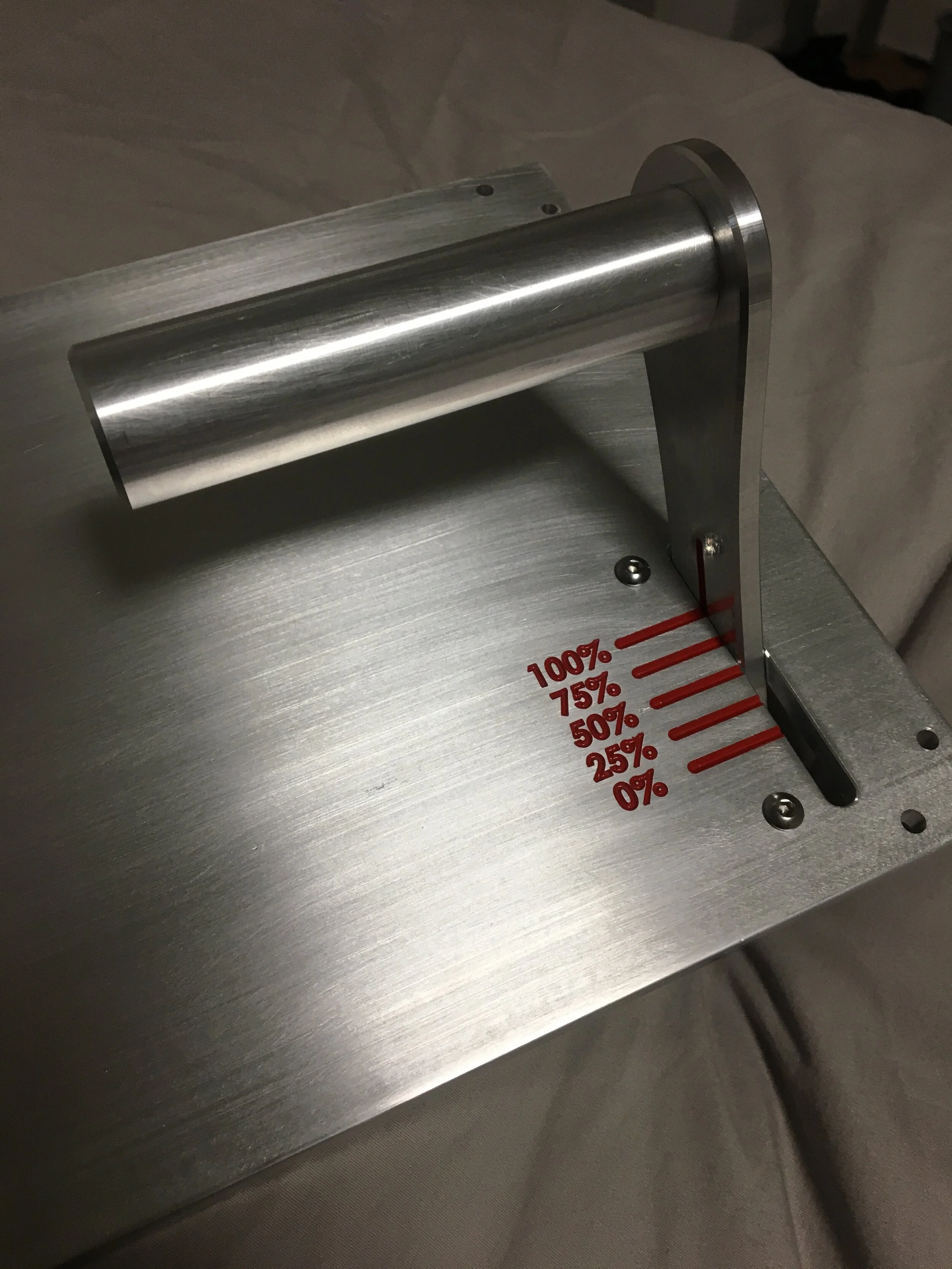
This is the throttle installed on the control panel. The text and lines were engraved with the CNC and filled it in with paint. I am glad I made my own throttle assembly - it turned out really nice, and it has stays in place in rough waves, feels really good in the hand unlike the commercially available throttle I’ve used, and it is a lot more compact. Also, it is fully sealed with many o-rings, and water that goes into the slot is contained and drains out the bottom of the control panel
Caltech Jellyfish cookie cutter

Top half of the Caltech research “jellyfish cookie cutter.” This device was made before I installed ball screws and got a vice so the tolerances are not as good as they are now. I designed this device to standardize and simplify the process of removing jelleyfish limbs for studies in regeneration conducted by Professor Geontoro’s research group in the Geontoro Lab at Caltech. I worked in this lab during high school.
The video above shows the machining of the top part of the Caltech jelly fish cookie cutter.