PLC Control Systems
I am using PLCs and an HMI along with some accompanying circuitry to control the rudders and maneuvering thrusters servos and pneumatics . Additionally, I’m using microcontrollers for other systems - more on my circuit design page.
Engine Compartment Electronics
This PLC and accompanying servo drivers control the rudders and maneuvering thruster servos. Additionally, it controls the pneumatic actuators with solenoids (some shown here.) This PLC talks to the HMI and PLC in the main control panel (under the dashboard).
This electronic box houses the servo drives and a PLC, which is connected to the HMI on the main control panel.
Above: some of the wiring behind the main control panel.
Wiring diagram for the engine compartment PLC.
Programming the PLCs
The PLCs I used are from Velocio. I used their software to program the PLC and optimized my code to run fast. I checked how many times my code ran in a second with an oscilloscope. Every time the program completed a full loop, it output a signal that I picked up with my oscilloscope.
This is the main program for the front PLC (in the main control panel.) To make the program run faster, I made multiple subprograms and only ran each subprogram every so often, reserving more processor time for my critical subprograms thereby allowing them to run more often.
I measured the time each subprogram took to complete and was able to optimize my program to run about 500 times a second. I also reduced the lag due the program saving data to its memory.
Front PLC and Control panel electronics
Below is the front panel (dashboard) that has the steering wheel and a touch screen (HMI) for controlling the boats various systems.
This is the steering wheel I made, with a custom bearing and O-ring. The ring is mainly for friction so the wheel stays still when the boat rocks in waves. The ring also is for sealing water out. This is not the proper use of an O-ring because its application should be static.
Emergency-Stop button to stop all the thrusters, rudders and engine.
Control panel switches.
Wiring behind control panel HMI.
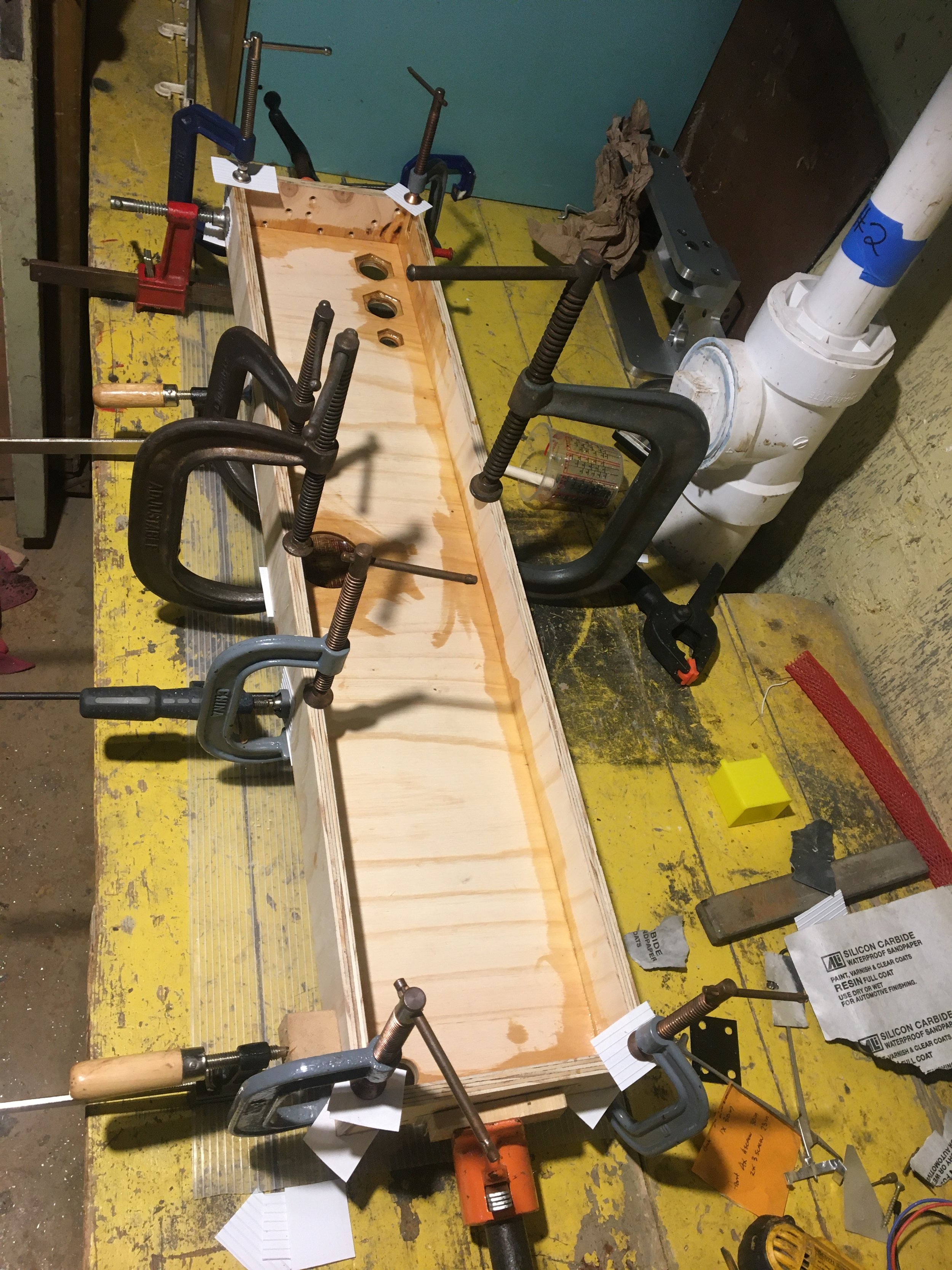
A step in the construction of the control panel box.
Boat’s main engine throttle.
Front PLC (in the main control panel) wiring diagram. In the future, more wiring will be added to the front PLC, but the back PLC is now mostly done.
Early HMI software (touch screen controller), showing the rudder settings page.


