Circuit Design
For my 25ft boat Daedalus, I designed and built over 10 PCBs. Additionally, the boat has an extensive sensor array built into the hull. Here are the highlights.
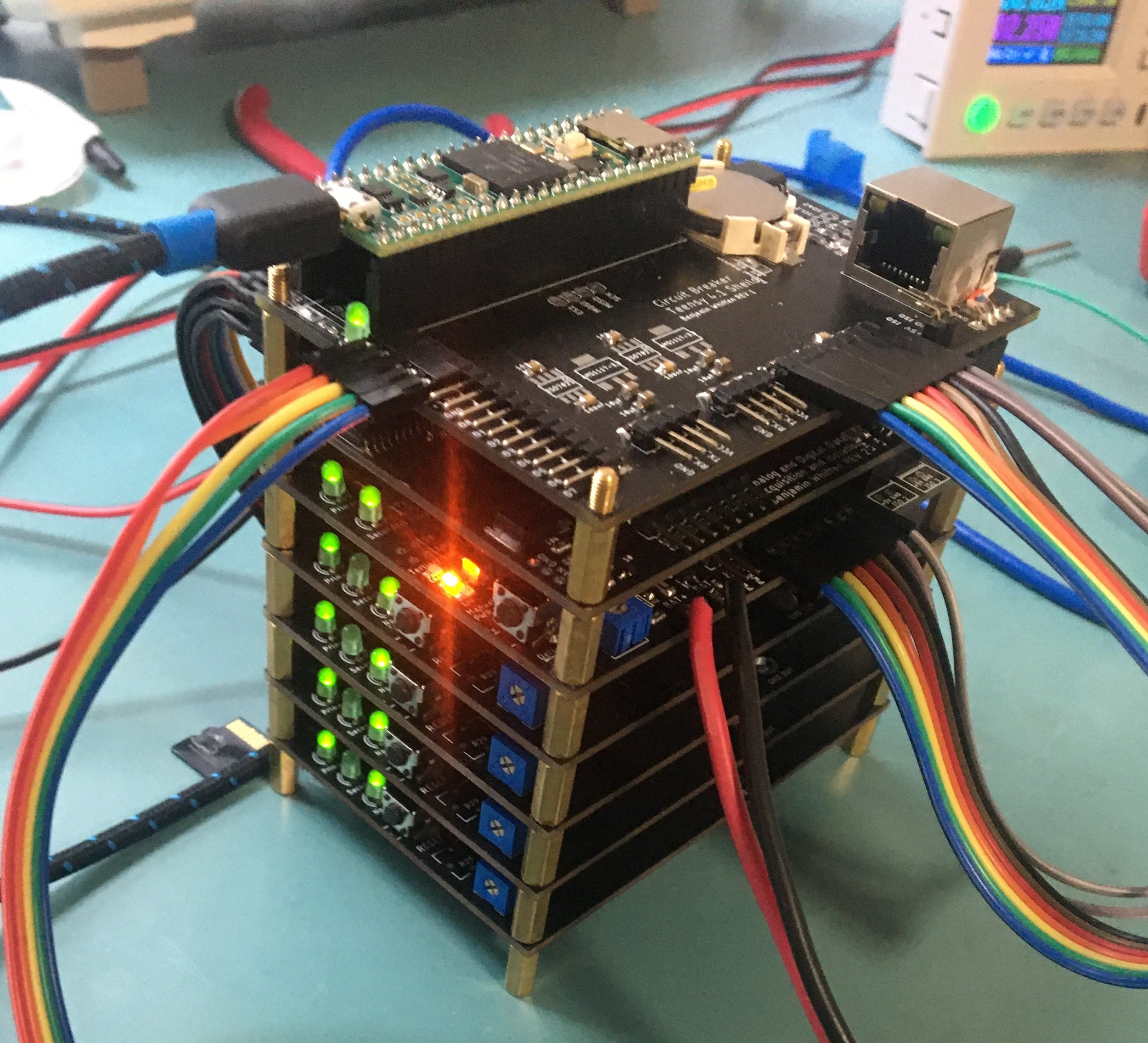
Digital Circuit Breaker
Automatically switches between two power sources in a few microseconds in the event of a failure.
Measures current draw configurable to ranges of a few mA to 30A.
Shuts the circuit off in microseconds if overcurrent is detected with configurable delay.
Each circuit breaker draws less than 1 mA while running and is designed to be very power efficient. All logic is implemented with low-power circuits and MOSFETs.
Each circuit breaker can be remotely controlled to power on and off systems and be reset or put in a low power mode.
Stack of 4 circuit breaker boards, power, isolator and controller board.
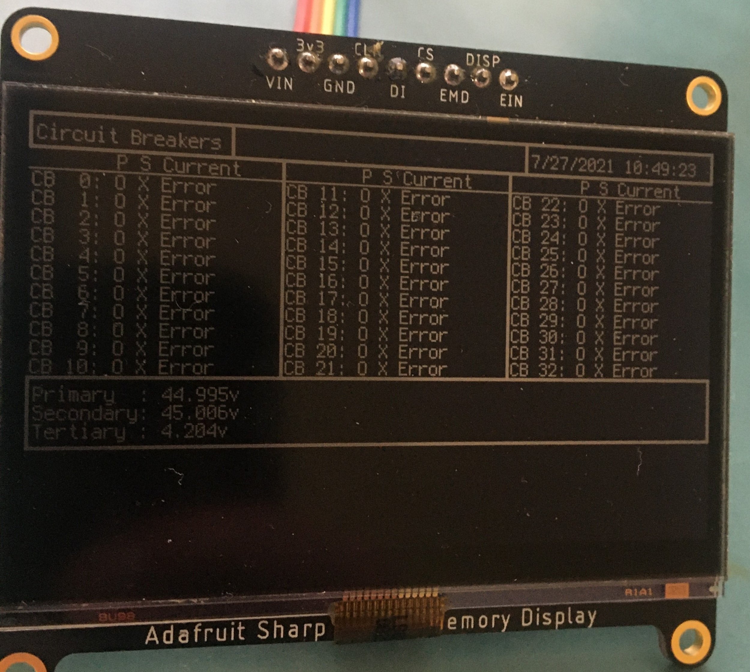
Display for circuit breakers, displaying status. The display allows for turning systems on and off or switching power supplies.
Guidance Computer
This calculates a course to stay on a waypoint mission and sends commands to the boat’s PLCS, where the rudders are controlled via PID. It works well out on the water!
100W LED Driver
This is a prototype for a custom LED light driver board to power the 25 100W LED on my boat. It still needs some work, as you can see by the soot.
Guidance computer withs its case open.
Fried 100W LED driver prototype.
LED Controller board
There are 25 100-watt LEDs embedded in the hull of my boat; each one has 3 temperature sensors (redundant). Additionally, throughout the hull, there are moisture sensors for detecting leaks. All these sensors need to be monitored, which is why I designed two PCBs that are stackable to read the data from the 100+ sensors in my array. To read so many (analog and digital) sensors with a single microcontroller, I used many multiplexers and SPI ADC. In total, there is over 1 mile of wires embedded in the hull of the boat.
System hooked up to my boat, reading hull moisture data. This system allowed me to discover some trapped moisture in parts of the hull before it caused damage to the boat.
Boat hull under construction: later on the space between all the ribs visible above will be filled with closed bubble foam. The red circles show where each outward facing 100W LED is located, and the green circles show where others will be installed later on in the process.
One of the ~40 hull moisture sensors (blue).
Power protection board circuit on bottom board next to the multiplexers. This circuit immediately cuts power if a short is detected.
Close-up of a single 100-watt LED assembly with a water block for cooling and power and temperature sensors in place. This assembly is located behind a small window facing out of the hull.
Wires from all the sensors embedded in the hull of the boat.


